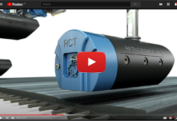
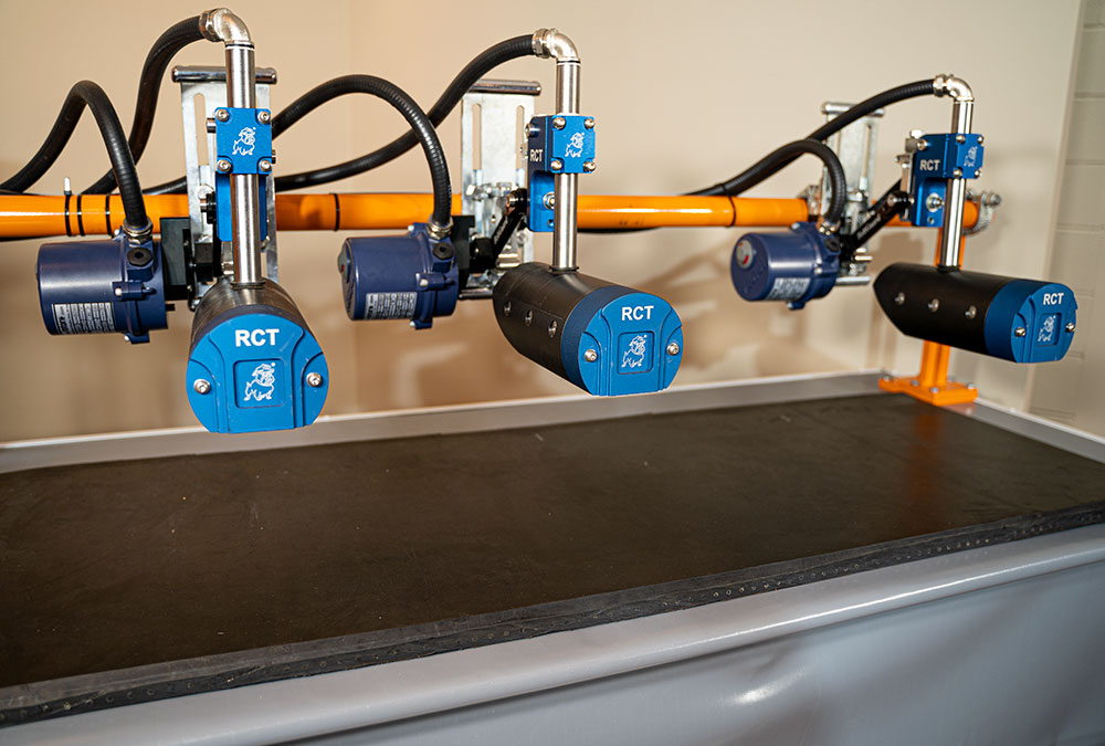
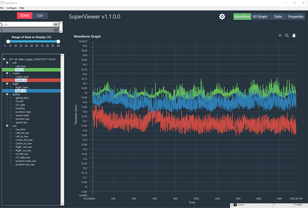
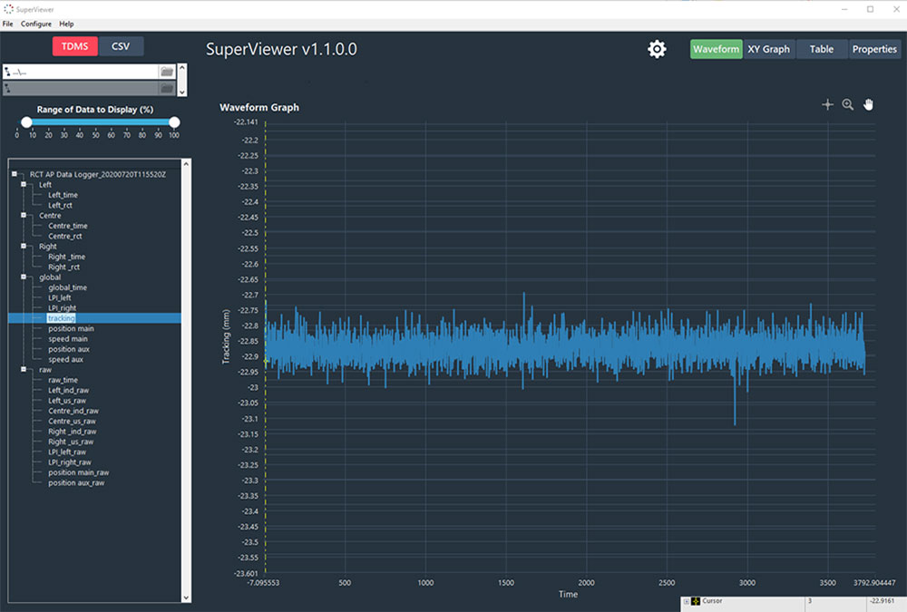
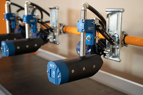
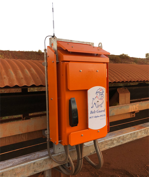
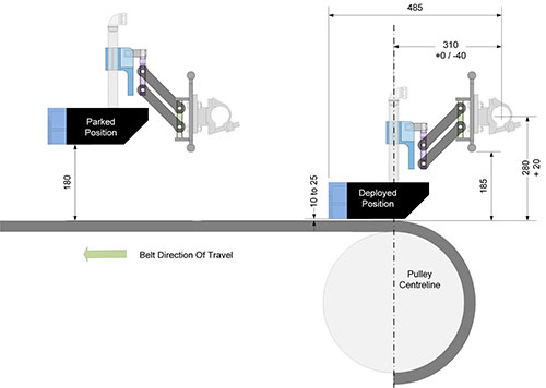
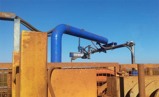
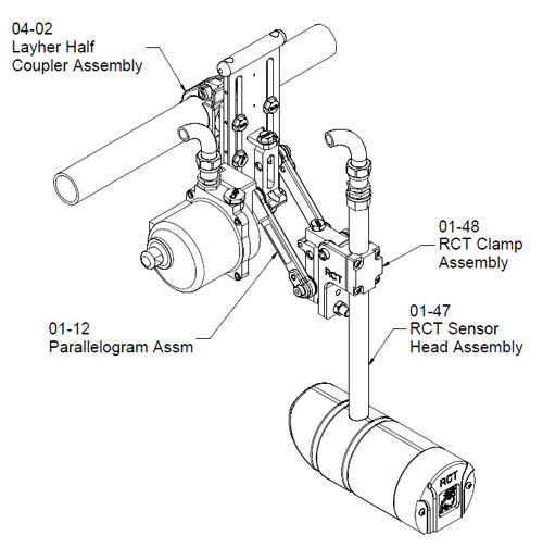
The primary purpose of the device is to identify points of thinnest cover along the endless belt length. These points should then become the locations for future static lateral cover thickness measurements. However, regular RCT scanning will provide the information necessary to predict the end-of-life in a belt cover, when trended with other appropriate duty information, such as time and tonnage. This feature may render regular multi-location lateral cover thickness measurements unnecessary. The device is permanently mounted on the conveyor structure. When not actually performing a scan, the Sensor Heads are parked at a conservative distance from the belt surface. Scanning can be performed ‘on demand’ or at operator-set intervals. During a scan the Sensor Heads are “Deployed” and then sit ~30.0mm above the tops of the steel cords. Following a scan, the Sensor Heads are automatically “Parked” as described above. With a pair of Lateral Position Indicators (LPIs) fitted, the RCT can track the belt's lateral movement, allowing deployment when the belt is correctly positioned on the structure. As well as producing a tracking signature of the conveyor, this also ensures repeatability in the data. Each Sensor Head contains the probes necessary to make the cover thickness measurements. The Sensor Heads each measure a strip of belting ~100mm wide across the belt. A decision needs to be made as to which 100mm strips of belt width are to be measured, the ‘preferred lateral positions’. This decision is based on historical lateral cover profile measurements. Normally, site interest will be in the area of maximum wear across the belt width, i.e. thinnest cover. Both skirts of the conveyor can also be monitored for any accelerated excessive wear of the belting. The Main Electrical Enclosure or MEE contains the processing electronics and data storage. It also contains the Communication Module, which is used to access the device for data download. Access to the system is via a Windows-based application or Web-Interface. Other Industry standards of connection are available upon request. Software and firmware upgrades are done remotely and there is provision for simple on-site re-calibration if the need arises. An optional 4-20mA output, proportional to cover thickness, is also available in real-time. Installation is usually carried out by site personnel under the supervision of a Beltscan product specialist. The Sensor Head is typically located above a major pulley and is positioned laterally over the thinnest strip of belting. Conveyor specific mounting hardware needs to be provided by site An IP Surveillance camera is provided with each system to confirm the belt is clean before deployment. The RCT Alpha-PLUS equipment requires very little maintenance other than general housekeeping by ensuring the system is kept relatively free from product build-up etc. Visual inspection should be carried out on a regular basis to confirm all mounts are secure and that the actuator operates freely. A regular light hose down is recommended. The RCT Alpha-PLUS is a software-based device.
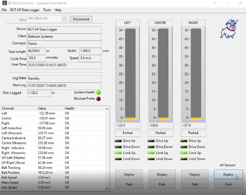
All device configuration and operation is performed under Belt Guard Boss – Client software, which is supplied with the device. Belt Guard Boss is accessible via a PC on the same network as the RCT Alpha-PLUS. Analysis and report generation can be done in-house, or outsourced to Beltscan Systems for a monthly fee by arrangement. RCT Cover Care is full featured service that allows automated scans and reporting of the customers selected conveyor belts.
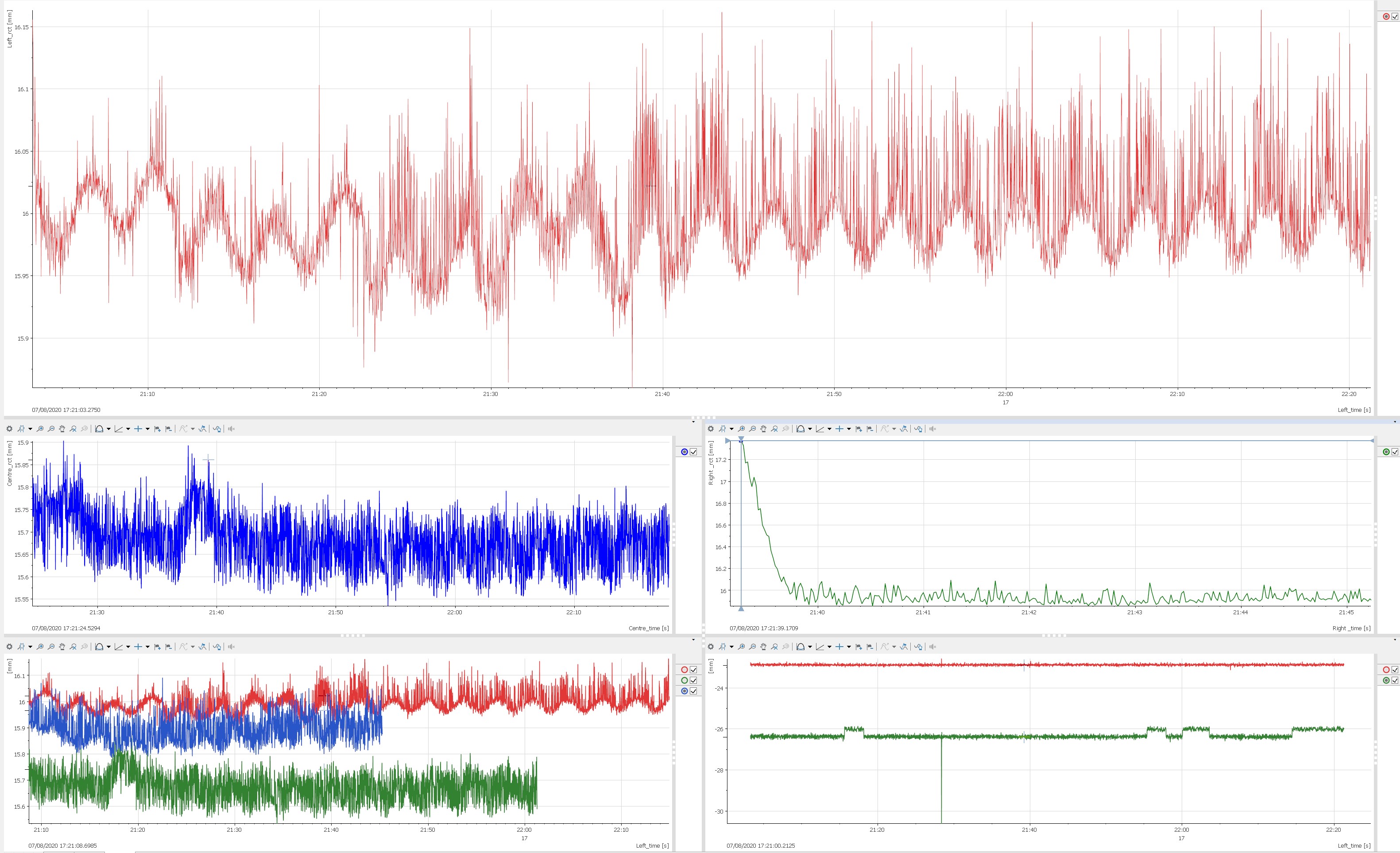
The RCT Hardware and software is provided and installation of the device is performed by site personnel. For a service fee, reports are automatically generated and issued to site on a daily, weekly or monthly basis.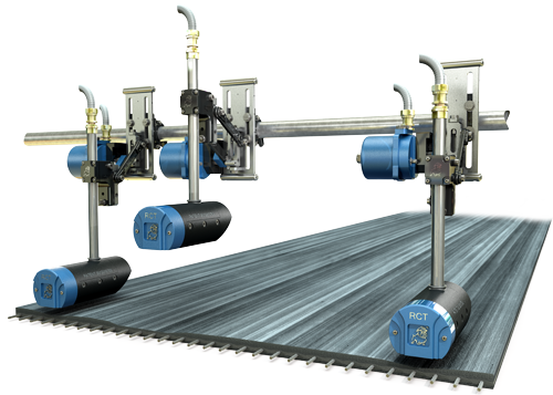
How it Works
![]()
Belt Tracking / Wander
Sensor Head
Communications
Installation
Maintenance
Software
Technical Specifications
Application
Belt Type
Steel Cord
Belt Width
No Limit
Belt Length
No Limit
Belt Speed
No Limit
Main Electrical Enclosure
Construction
304 Grade Stainless Steel IP66 (NEMA4)
Size (mm)
400 x 400 x 440 (No Weather Shields)
Electronics
Power Supply
110/220 VAC 60/50Hz or 24VDC
Power
~25W
Communications
TCP/IP Ethernet, 4-20mA, Modbus
Operating Temperature
-13 ~ 158°F(-25 ~ 70°C), 5 to 95% RH
Storage Temperature
-13 ~ 158°F(-25 ~ 70°C), 5 to 95% RH
RCT Cover Care
-
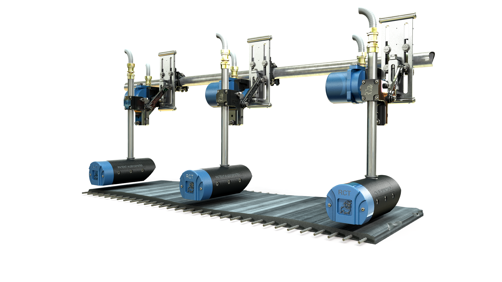
RCT Alpha-PLUS
3 Locations Non-contact Permanently Installed Data Captured with Belt Running
